Subaru Crosstrek Service Manual: Inspection
HVAC SYSTEM (HEATER, VENTILATOR AND A/C) > Control Panel
INSPECTION
1. CHECK ILLUMINATION
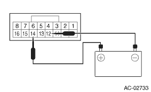
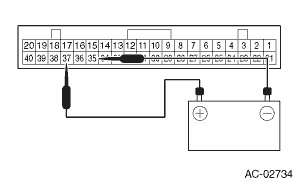
1. Check the illumination operation when battery voltage is applied between the terminals of control panel.
• Manual A/C model
Terminal No. | Inspection conditions | Specification | Connection diagram |
14 (+) — 12 (−) | Connect battery to the terminals | Light ON |
• Auto A/C model
Terminal No. | Inspection conditions | Specification | Connection diagram |
37 (+) — 35 (−) | Connect battery to the terminals | Light ON |
2. If it does not operate normally, replace the heater control assembly.
2. BLOWER SWITCH (MANUAL A/C MODEL)
1. Measure the resistance between the control panel terminals.
Preparation tool:
Circuit tester
Terminal No. | Inspection conditions | Standard | Connection diagram |
— | OFF | — | — |
1 — 2, 4 | 1 (LO) | Less than 1 ? |

1 — 3, 4
2 (M1)
Less than 1 ?

1 — 4, 6
3 (M2)
Less than 1 ?
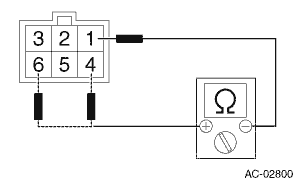
1 — 4, 5
4 (HI)
Less than 1 ?

2. Replace the heater control assembly if the inspection result is not within the standard.
 Control panel
...
 Removal
HVAC SYSTEM (HEATER, VENTILATOR AND A/C) > Control PanelREMOVALCAUTION:Before handling the airbag system components, refer to “CAUTION” of “General Description” in “AI ...
Other materials:
Keyless access system check Operation
KEYLESS ACCESS WITH PUSH BUTTON START SYSTEM (DIAGNOSTICS) > Keyless Access System CheckOPERATION1. On «Start» display, select «Diagnosis».2. On «Vehicle selection» display, input the target vehicle information and select «Confirmed».3. On «Main Menu» display, select «Each System».4. ...
Component
COOLING(H4DO) > General DescriptionCOMPONENT1. WATER PUMP(1)Water pump pulley(13)Clip(25)Gasket(2)Water pump ASSY(14)Water pipe hose RH(26)Engine coolant temperature sensor(3)Gasket(15)Water pipe ASSY (CVT model)(27)EGR control valve(4)Thermostat (engine side)(16)Preheater hose A(28)O-ring(5)Gask ...
Installation
CONTINUOUSLY VARIABLE TRANSMISSION(TR580) > Secondary Pressure SensorINSTALLATIONCAUTION:• Be sure to prevent water or oil from contacting the connector terminal of secondary pressure sensor. If adhesion occurs, replace with a new part.• After installing the secondary pressure sensor, ...