Subaru Crosstrek Service Manual: Disassembly
STARTING/CHARGING SYSTEMS(H4DO) > Generator
DISASSEMBLY
1. Remove the cap from the generator.

2. Remove four bolts.

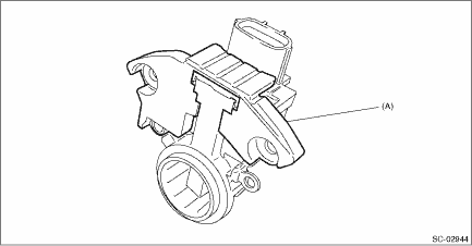
3. Use a drier to heat the rear cover (A) portion to 50 — 60°C (122 — 140°F).
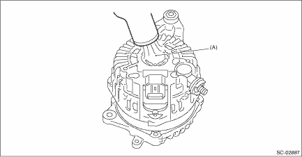
4. Insert a flat tip screwdriver or similar tool wrapped with protective tape into the gap between stator core and the front cover to disassemble.

(A) | Flat tip screwdriver |
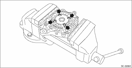
5. Hold the rotor on a vise and remove the pulley.
CAUTION:
When holding the rotor with a vise, place aluminum plates or wooden pieces on the vise jaws to prevent rotor from damage.

6. Remove the rotor from the front cover.
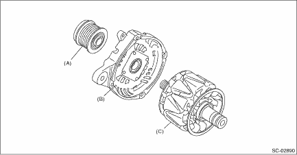
(A) | Pulley | (B) | Front cover | (C) | Rotor |
7. Use the following procedures to remove the ball bearings.
(1) Remove the bolt, and then detach the bearing retainer.
(2) Firmly attach an appropriate tool (such as a correct size socket wrench) to the bearing inner race.

(3) Use the press to push the ball bearings out from the front cover.
8. Using the bearing puller, remove the bearings from the rotor.

9. Remove six bolts which connect the rectifier and stator coil, then remove the stator coil.

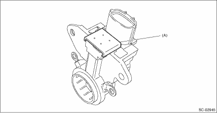
10. Remove four screws which secure the IC regulator to the rear cover, then remove the IC regulator.
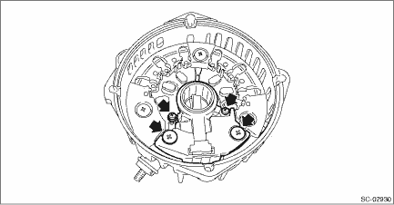
11. Use the following procedures to remove the brush.
(1) Remove the cover A.
(A) | Cover A |
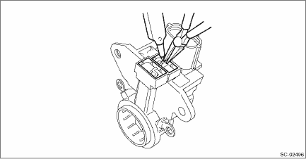
(2) Remove the cover B.
(A) | Cover B |
(3) Disconnect the connection and remove the brush.
12. Remove the rectifier as follows.
(1) Remove the cover on terminal B.

(2) Remove the nut on terminal B.
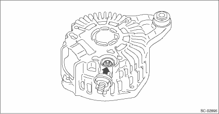
(3) Remove the bolts which secure the rectifier, and remove the rectifier.

 Removal
STARTING/CHARGING SYSTEMS(H4DO) > GeneratorREMOVAL1. Remove the V-belt covers.2. Disconnect the ground cable from battery. NOTE">3. Remove the V-belts. V-belt > REMOVAL">4. Dis ...
 Inspection
STARTING/CHARGING SYSTEMS(H4DO) > GeneratorINSPECTION1. DIODECAUTION:There is the possibility of damaging the diodes if a mega-tester (used to measure high voltages) or a similar measuring instrume ...
Other materials:
List of diagnostic trouble code (dtc) List
INSTRUMENTATION/DRIVER INFO (DIAGNOSTICS) > List of Diagnostic Trouble Code (DTC)LISTDTCItemContentReferenceU0073CONTROL MODULE COMMUNICATION BUS OFFDetected when CAN line abnormality is detected. Diagnostic Procedure with Diagnostic Trouble Code (DTC) > DTC U0073 CONTROL MODULE COMMUNICATION ...
Installation
FUEL INJECTION (FUEL SYSTEMS)(H4DO) > Fuel PumpINSTALLATION1. Install the fuel pump assembly to the fuel tank.(1) Make sure the sealing portion is free from fuel or foreign matter before installation.(2) Align the protrusion (A) of the gasket to the position shown in the figure, and install the g ...
Dtc b2814 power supply low voltage
EyeSight (DIAGNOSTICS) > Diagnostic Procedure with Diagnostic Trouble Code (DTC)DTC B2814 POWER SUPPLY LOW VOLTAGEDetected when the status of 7.0 V or less continues approximately for 5 seconds and is judged to be low-voltage malfunction, or when the +B harness of the stereo camera is broken.DTC ...