Subaru Crosstrek Service Manual: Assembly
CONTROL SYSTEMS > MT Gear Shift Lever
ASSEMBLY
NOTE:
• Clean all the parts before assembly.
• Apply NIGTIGHT LYW No. 2 grease or equivalent to each part. General Description > COMPONENT">
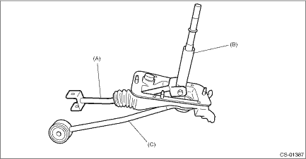
1. Mount the bushing and cushion rubber to the stay.

(A) | Bushing |
(B) | Stay |
(C) | Cushion rubber |
2. Install the bushing and spacer to boss.

(A) | Bushing |
(B) | Spacer |
3. Install the boss to the joint.
NOTE:
Use a new self-locking nut.
Tightening torque:
12 N·m (1.2 kgf-m, 8.9 ft-lb)

4. Install the snap ring to gear shift lever and install the bushing.
NOTE:
Apply grease to the bushing.

(A) | Spring pin |
(B) | Bushing |
(C) | Snap ring |
5. Apply grease to the bushing and O-ring, and then install to gear shift lever.

(A) | O-ring |
(B) | Bushing |
6. Apply sufficient grease into boss, and then install the gear shift lever to the stay.

7. Install the snap ring.

(A) | Snap ring |
8. Insert the gear shift lever and rod into boot hole.
9. Install the rod.
NOTE:
Use a new self-locking nut.
Tightening torque:
12 N·m (1.2 kgf-m, 8.9 ft-lb)
(A) | Rod |
(B) | Lever |
(C) | Stay |
10. Install the lock wire.
NOTE:
Use a new lock wire.

(A) | Lock wire |
NOTE:
• Install the lock wire to the stay groove.
• Bend the extra wire to the same direction of lock wire winding.

(A) | Inner boot |
(B) | Lock wire |
(C) | Stay |

 Removal
CONTROL SYSTEMS > MT Gear Shift LeverREMOVAL1. Disconnect the ground cable from battery. NOTE">NOTE:For model with battery sensor, disconnect the ground terminal from battery sensor.2. Rem ...
Other materials:
Electrical specification
OCCUPANT DETECTION SYSTEM (DIAGNOSTICS) > Control Module I/O SignalELECTRICAL SPECIFICATIONCAUTION:Never remove the occupant detection control module, occupant detection sensor or seat frame because they are integrated into one unit.Terminal No.Terminal nameInput/Output valueNote1Airbag CM commun ...
Dtc c0033 fl hold valve malfunction
VEHICLE DYNAMICS CONTROL (VDC) (DIAGNOSTICS) > Diagnostic Procedure with Diagnostic Trouble Code (DTC)DTC C0033 FL HOLD VALVE MALFUNCTIONNOTE:For the diagnostic procedure, refer to “C0064 NORMAL CLOSING VALVE 2 MALFUNCTION”. Diagnostic Procedure with Diagnostic Trouble Code (DTC) > ...
Installation
LIGHTING SYSTEM > Front Fog Light BulbINSTALLATIONCAUTION:• After connecting the connector, make sure that the bulb is locked securely.• Install the mud guard - front so that the front end of the mud guard (b) comes outside the bumper face - front (a).Install each part in the reverse ...