Subaru Crosstrek Service Manual: Removal
MECHANICAL(H4DO) > Cylinder Head
REMOVAL
1. CYLINDER HEAD RH
1. Remove the engine from the vehicle. Engine Assembly > REMOVAL">
2. Remove the intake manifold. Intake Manifold > REMOVAL">
3. Remove the engine wiring harness. Engine Wiring Harness > REMOVAL">
4. Remove the tumble generator valve assembly RH. Tumble Generator Valve Assembly > REMOVAL">
5. Remove the chain cover. Chain Cover > REMOVAL">
6. Remove the rocker cover RH. Rocker Cover > REMOVAL">
7. Remove the cam carrier RH. Cam Carrier > REMOVAL">
8. Remove the EGR cooler. EGR Cooler > REMOVAL">
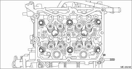
9. Loosen the bolts holding the cylinder head RH equally, a little at a time in numerical sequence as shown in the figure, and while leaving the cylinder head bolts (1) and (4) engaged by three or four threads, remove the other cylinder head bolts.
NOTE:
Leaving the cylinder head bolts (1) and (4) engaged by three or four threads prevents the cylinder head RH from falling.

10. While tapping the cylinder head RH with a plastic hammer, separate it from cylinder block RH.
11. Remove the bolts (1) and (4) to remove cylinder head RH.
12. Remove the cylinder head gasket RH.
CAUTION:
Be careful not to scratch the mating surface of cylinder head and cylinder block.
13. Remove the liquid gasket from cylinder head RH and cam carrier RH.
2. CYLINDER HEAD LH
1. Remove the engine from the vehicle. Engine Assembly > REMOVAL">
2. Remove the intake manifold. Intake Manifold > REMOVAL">
3. Remove the engine wiring harness. Engine Wiring Harness > REMOVAL">
4. Remove the tumble generator valve assembly LH. Tumble Generator Valve Assembly > REMOVAL">
5. Remove the chain cover. Chain Cover > REMOVAL">
6. Remove the rocker cover LH. Rocker Cover > REMOVAL">
7. Remove the cam carrier LH. Cam Carrier > REMOVAL">
8. Remove the A/C compressor. Compressor > REMOVAL">
9. Loosen the bolts holding the cylinder head LH equally, a little at a time in numerical sequence as shown in the figure, and while leaving the cylinder head bolts (1) and (4) engaged by three or four threads, remove the other cylinder head bolts.
NOTE:
Leaving the cylinder head bolts (1) and (4) engaged by three or four threads prevents the cylinder head LH from falling.
10. While tapping the cylinder head LH with a plastic hammer, separate it from cylinder block LH.
11. Remove the cylinder head bolts (1) and (4) to remove cylinder head LH.
12. Remove the cylinder head gasket LH.
CAUTION:
Be careful not to scratch the mating surface of cylinder head and cylinder block.
13. Remove the liquid gasket from cylinder head LH and cam carrier LH.
 Assembly
MECHANICAL(H4DO) > Cylinder HeadASSEMBLY(1)Exhaust valve(6)Valve spring(11)Intake valve guide(2)Intake valve(7)Valve spring retainer(12)Exhaust valve guide(3)Cylinder head(8)Valve collet(13)Roller ...
 Disassembly
MECHANICAL(H4DO) > Cylinder HeadDISASSEMBLY1. Remove the chain cover securing bolt from the cylinder head LH.2. Remove the stud bolts from the cylinder head.3. Remove the valve collet, valve, valve ...
Other materials:
Dtc c0057 vdc interrupted due to egi reason
VEHICLE DYNAMICS CONTROL (VDC) (DIAGNOSTICS) > Diagnostic Procedure with Diagnostic Trouble Code (DTC)DTC C0057 VDC INTERRUPTED DUE TO EGI REASONDTC DETECTING CONDITION:Cooperation control prohibition of ECMTROUBLE SYMPTOM:• VDC does not operate.• EyeSight does not operate.NOTE:• ...
Relay and fuse
Inspection
CRUISE CONTROL SYSTEM > Relay and FuseINSPECTION1. CHECK FUSE1. Remove the fuse and inspect visually.2. If the fuse is blown out, replace the fuse.NOTE:If the fuse is blown again, check the system wiring harness. Location
CRUISE CONTROL SYSTEM > Relay and FuseLOCATIONRelay & f ...
Connecting and disconnecting a USB memory/portable device
The USB port and the AUX jack are
located as shown in the following illustration.
NOTE
This unit does not support commercially
available USB hubs.
Turn on the power of the device
when it is not turned on.
This device has a USB port for USB
memory/portable device.
For compatible ...
